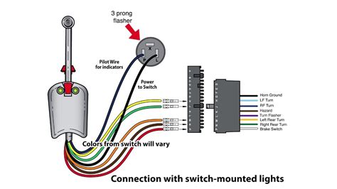
The universal turn signal switch is an essential component in any vehicle's electrical system. It plays a crucial role in controlling the turn signals, hazard lights, and sometimes even the headlights. Understanding how to wire a universal turn signal switch is vital for any car enthusiast or DIY mechanic. In this article, we will delve into the world of turn signal switch wiring and provide you with a comprehensive guide on how to wire a universal turn signal switch.
Understanding the Universal Turn Signal Switch
Before we dive into the wiring process, let's take a closer look at the universal turn signal switch itself. The switch typically consists of a rotary dial or a toggle switch that controls the turn signals and hazard lights. Some switches may also have additional features, such as a dimmer switch for the headlights.
The universal turn signal switch is designed to be adaptable to various vehicles, making it a popular choice among car enthusiasts and DIY mechanics. However, this adaptability also means that the wiring process can be more complex than usual.

Wiring Diagrams and Schematics
To wire a universal turn signal switch, you'll need to refer to the wiring diagrams and schematics provided by the manufacturer. These diagrams will show you the correct wiring configuration for your specific switch.
Typically, the wiring diagram will include the following:
- The battery connection
- The turn signal lights (left and right)
- The hazard lights
- The headlight connection (if applicable)
- The ground connection
Step-by-Step Wiring Process
Now that we have a basic understanding of the universal turn signal switch and its wiring diagrams, let's move on to the step-by-step wiring process.
Step 1: Connect the Battery
The first step is to connect the battery to the turn signal switch. This is usually done by connecting the positive battery cable to the switch's battery terminal.

Step 2: Connect the Turn Signal Lights
Next, connect the turn signal lights to the switch. The left and right turn signal lights are usually connected to separate terminals on the switch.

Step 3: Connect the Hazard Lights
The hazard lights are usually connected to a separate terminal on the switch. Make sure to connect the hazard lights to the correct terminal to avoid any wiring issues.

Step 4: Connect the Headlights (if applicable)
If your switch has a headlight connection, connect the headlights to the correct terminal on the switch.

Step 5: Connect the Ground
Finally, connect the ground cable to the switch's ground terminal. This completes the wiring process.

Troubleshooting Tips
If you encounter any issues during the wiring process, here are some troubleshooting tips to help you resolve the problem:
- Double-check the wiring diagram and schematics to ensure you're connecting the wires correctly.
- Use a multimeter to test the voltage and continuity of the wires.
- Make sure the switch is properly seated and secured.
Conclusion
Wiring a universal turn signal switch can be a complex process, but with the right guidance, you can achieve a successful installation. Remember to refer to the wiring diagrams and schematics provided by the manufacturer, and follow the step-by-step wiring process outlined in this article.
If you're still unsure about any aspect of the wiring process, consider consulting a professional mechanic or seeking guidance from a car enthusiast community.


What is the purpose of a universal turn signal switch?
+A universal turn signal switch is a component that controls the turn signals, hazard lights, and sometimes even the headlights in a vehicle.
How do I wire a universal turn signal switch?
+To wire a universal turn signal switch, refer to the wiring diagrams and schematics provided by the manufacturer, and follow the step-by-step wiring process outlined in this article.
What are some common issues with universal turn signal switches?
+Common issues with universal turn signal switches include faulty wiring, worn-out contacts, and incorrect installation.
